Grupo 09 - Real-Time Localization System
![[Vídeo do projeto]](/projects/Group09/RTLS_Thumbnail.jpg)
| Equipa: |
Grupo 09: Adrian Jäger (Coord.) , Filipe Isaías , Gonçalo Tavares , João Cruz |
| Empresa: | Critical Manufacturing, SA |
| Orientadores: |
João Santos (Critical Manufacturing, SA)
Prof. Paulo Bartolomeu (DETI) Prof. Pedro Fonseca (DETI) |
The Real-Time Localization System (RTLS) project aims to develop a sophisticated solution for displaying the position of an Autonomous Intelligent Vehicle (AIV) and certain assets in a Digital Twin environment. The project is in collaboration with Critical Manufacturing, SA, with João Santos as the customer supervisor. The construction phase is progressing well, focusing on developing custom firmware for UWB nodes, operationalizing the gateway, and working on the user interface. Despite a deviation in the timeline for the frontend configuration, the project remains within budget, and the team anticipates meeting deadlines.
Challenge
The Real-Time Localization System (RTLS) project aims to create a UWB-based system for precise location identification within a designated space. In an open area serving as a system demonstrator, an Autonomous Intelligent Vehicle (AIV) lacks an efficient location reporting mechanism, prompting the need for a digital twin to showcase the exact location.
The project, which spans IT, electronics, and telecommunications, aims to create a UWB system that is roughly 10 m by 10 m in size. Real-time asset identification, including personnel, materials, and AIV, will be possible with this system thanks to data transferred over the MQTT protocol. For precise closed environment placement, the project needs knowledge of indoor location principles, communication systems (MQTT), and sensor integration.
Results
The project achieved several significant objectives:
A. Research
During the initial stage, we researched how the company wished to connect to the Digital Twin and what possibilities we had for Indoor Localization Services, concluding that UWB would be ideal, and that we should relay messages via MQTT.
B. Inception
During this second stage, a project plan was produced and agreed upon with the company. During the stage, a key milestone was accomplished:
Establishing a system architecture
The initial goal is to carefully plan a system architecture that combines UWB modules in the best possible way. This entails choosing our UWB modules carefully and creating a productive connecting scheme. We want to make sure that the modules communicate with each other without any problems and build a strong structure for sending information to the company’s system.
C. Construction
During this stage we achieved several objectives, including, but not limited to:
1. Configuring the Gateway
It was crucial to establish that the pre-configured image was working correctly to test the feasibility of our project. Furthermore, we also tested MQTT implementation.
2. Writing custom Firmware for the UWB Nodes
The investigation of UWB node firmware choices was one of the key objectives. We explore the complexities involved in creating specialised firmware to fulfil the unique requirements of our project. We’ve determined that the best options for obtaining exact location coordinates is Two-Way Ranging (TWR) with beacons after giving them significant thought. This choice is consistent with our aim to maintain a balance between synchronisation and precision.
3. Transferring data via MQTT
One essential component of our project goals, as determined by the company, is efficient data transfer. As we are committed to putting MQTT communication protocols into practice, making sure that data is sent between various system components in an efficient and dependable manner, the first thing we had to do was find the MQTT implementation and document all existing MQTT messages from the gateway. This goal improves the system’s overall efficacy and usability.
4. Creating a UI for configuration
Our objective here is to develop a user-friendly interface for configuring system parameters. This UI will allow those implementing this project in the field to easily manage and customize settings, enhancing the overall user experience. We strive to provide a straightforward and intuitive platform for efficient system setup and management.
5. Other achievements
✓ Read Accelerometer data and send to gateway;
✓ Create a 3D-printed case for the Rasp+UWB module;
✓ Add a map to UI;
✓ Add dynamic Node configuration to UI and MCU;
✓ Create Live overview on active nodes on UI.
D. Transition
For the transition stage, we created a webpage and a video to showcase our achievements.
Shape
Promotional Video
Learn more about our project from this promotional video:
Financial Status
Our budget of €500.00 by Critical Manufacturing allowed us to order all necessary parts, leaving a remaining balance of approximately €33.54.
| # | Category | Description | Status | Value |
|---|---|---|---|---|
| 1 | Hardware | Qorvo MDEK1001 development board kit | Acquired | €322.92 |
| 5 | Hardware | Li-Ion Battery 16340 | Acquired | €43.25 |
| 1 | Hardware | Raspberry Pi 4, to be swapped for Raspberry 3 | Acquired, to be returned | €49.99 |
| 1 | Hardware | SD-Card | Acquired, destroyed | €12.65 |
| 1 | Hardware | Pi Power Supply to be swapped for Micro USB Power Supply | Acquired | €9.75 |
| 1 | Hardware | Pi Case | Acquired | €4.00 |
| 4 | Hardware | UWB Anchor Power Supply | Acquired | €22.40 |
| 5 | Hardware | Pin Header 2x13 | Acquired | €1.50 |
| Total: | €466.46 |
In the beginning…
Before the start of the project, we had a call with Critical Manufacturing and were introduced to the project: The motivation, the concept, the technical details and the objectives!
.png)
.png)
.png)
.png)
.png)
Top Level Block Diagram
We also came a long way from our initial concept for the system, with our first ever top level block diagram envisioning a system in which one of the anchors serves as a gateway…
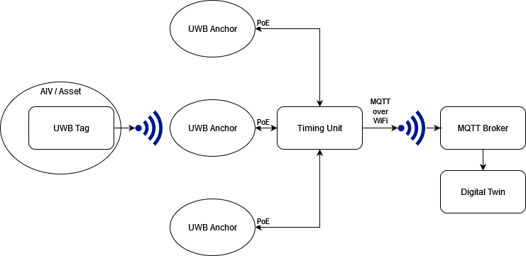
To our final version of the top level block diagram, where there is 1 single node serving as the bride of the gateway. However, the overall concept for our architecture remains unchanged:
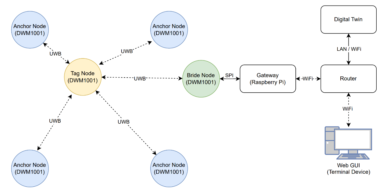
Gateway
So, what exactly is our gateway? The Gateway is a Raspberry Pi 3, and it is attached to a UWB Module, the bride node.
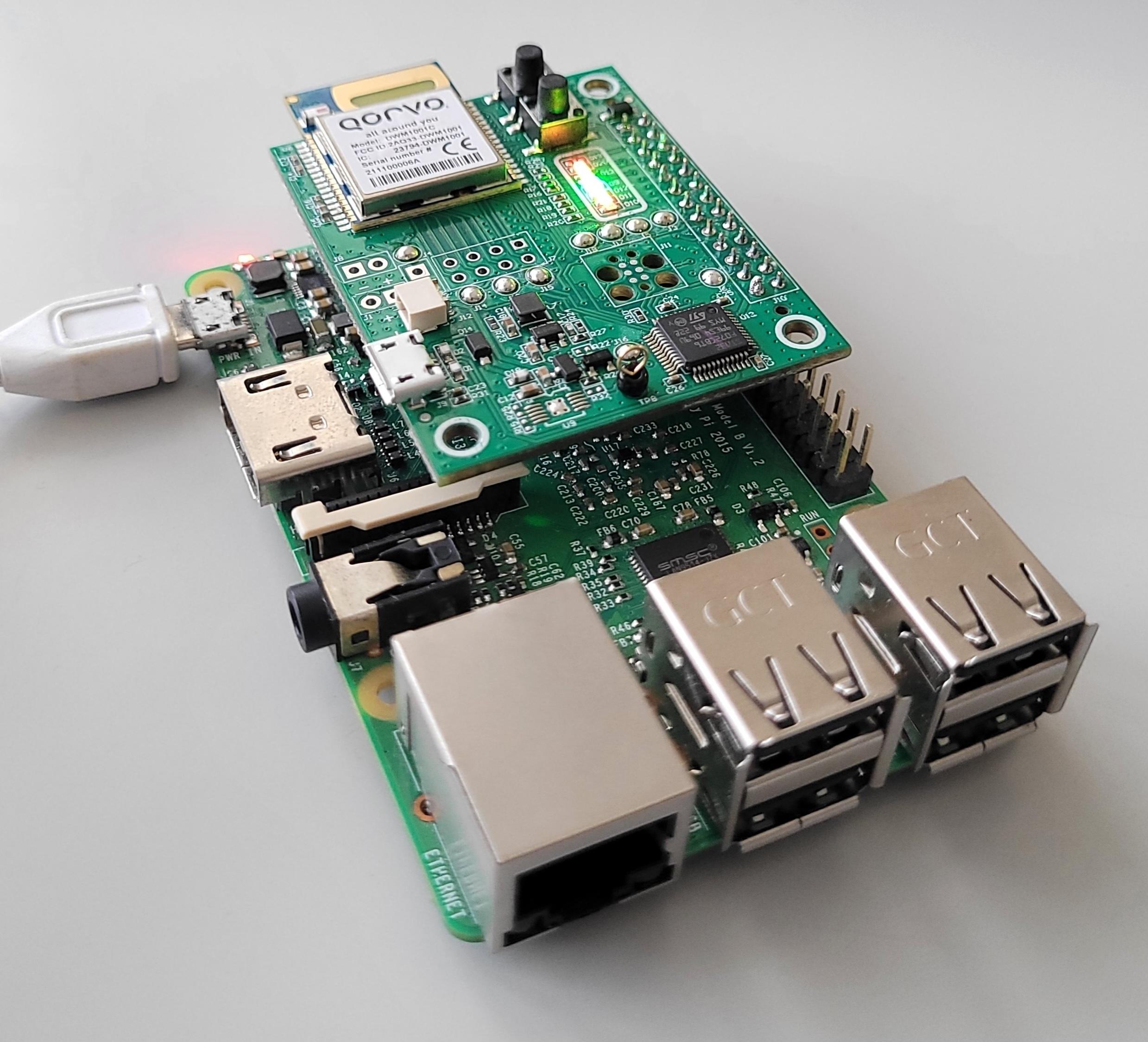
DWM1001 module
All the nodes are DWM1001 modules.
The DWM1001 module is a versatile and compact device designed for Ultra Wideband (UWB) applications, integrating Decawave’s DW1000 UWB transceiver IC along with other essential components. This module stands out for its IEEE 802.15.4-2011 UWB compliance, providing precise ranging accuracy up to 10cm. The inclusion of a Nordic Semiconductor nRF52832, Bluetooth® connectivity, and a motion sensor (3-axis accelerometer) enhances its capabilities for diverse applications. With a printed PCB antenna operating at 6.5 GHz, the DWM1001 supports a data rate of 6.8 Mbps.
</br>
The choice of the DWM1001 for your UWB project can be attributed to its comprehensive feature set. The module’s compact dimensions (19.1 mm x 26.2 mm x 2.6 mm), low power consumption in sleep mode (<15μA), and certification to ETSI, FCC, and ISED regulations make it an efficient and compliant solution. Its compatibility with various communication interfaces (SPI, UART, I2C, and Bluetooth®) facilitates seamless integration into your project. Additionally, the ready-to-go embedded firmware for Two Way Ranging Real-Time Location System (RTLS) applications, along with APIs for user code customization, accelerates the design cycle, reduces development costs, and shortens the time to market, making it a compelling choice for UWB projects.
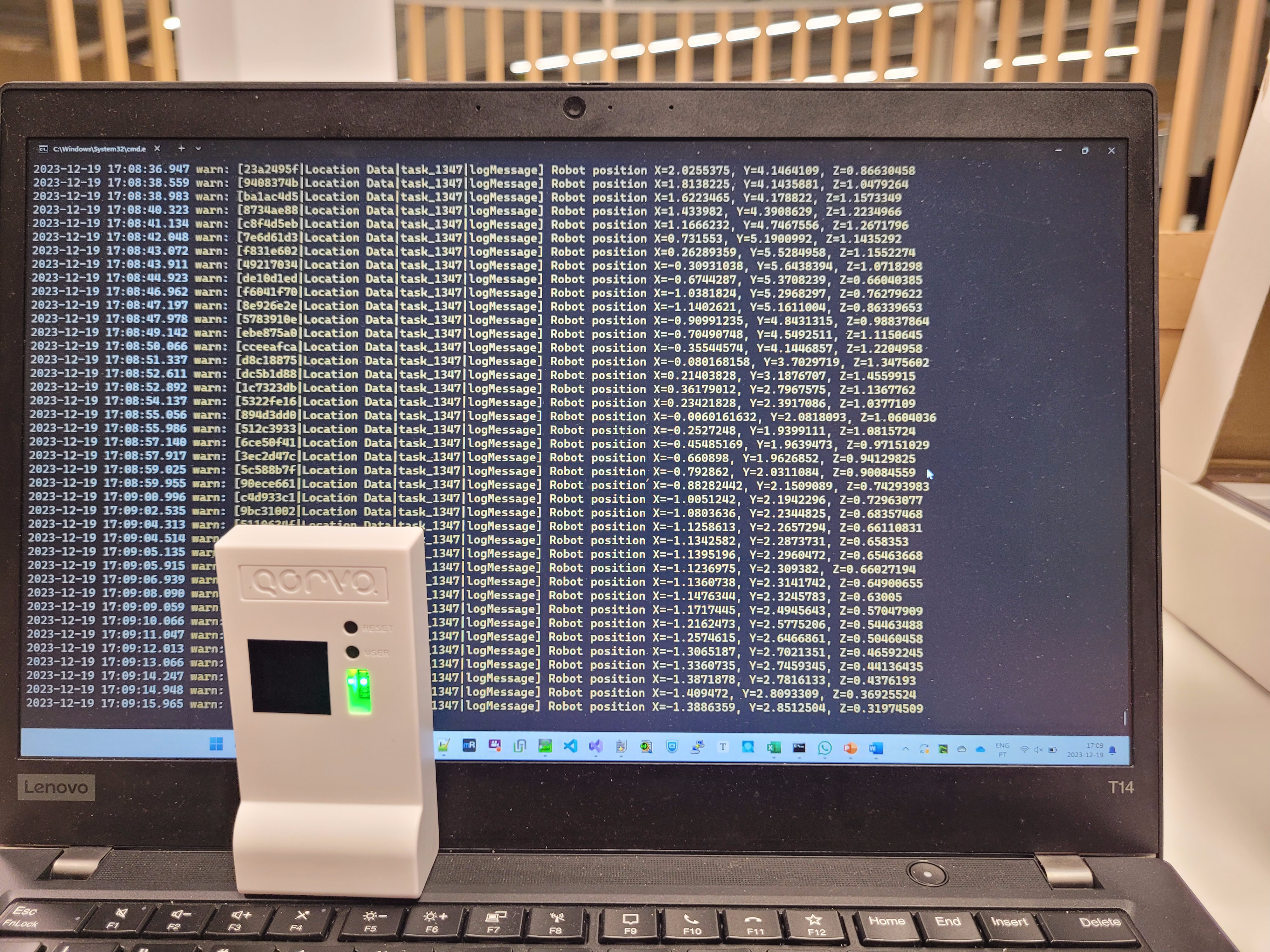
From the initial tests…
We were able to establish that our system could function given pre-packaged functions, which let us conclude we had correctly configured the Raspberry Pi:
To the final UI and tests
Critical Manufacturing Visit
Towards the end of the semester, we paid a visit to Critical Manufacturing and did an in-situ test, documented here:
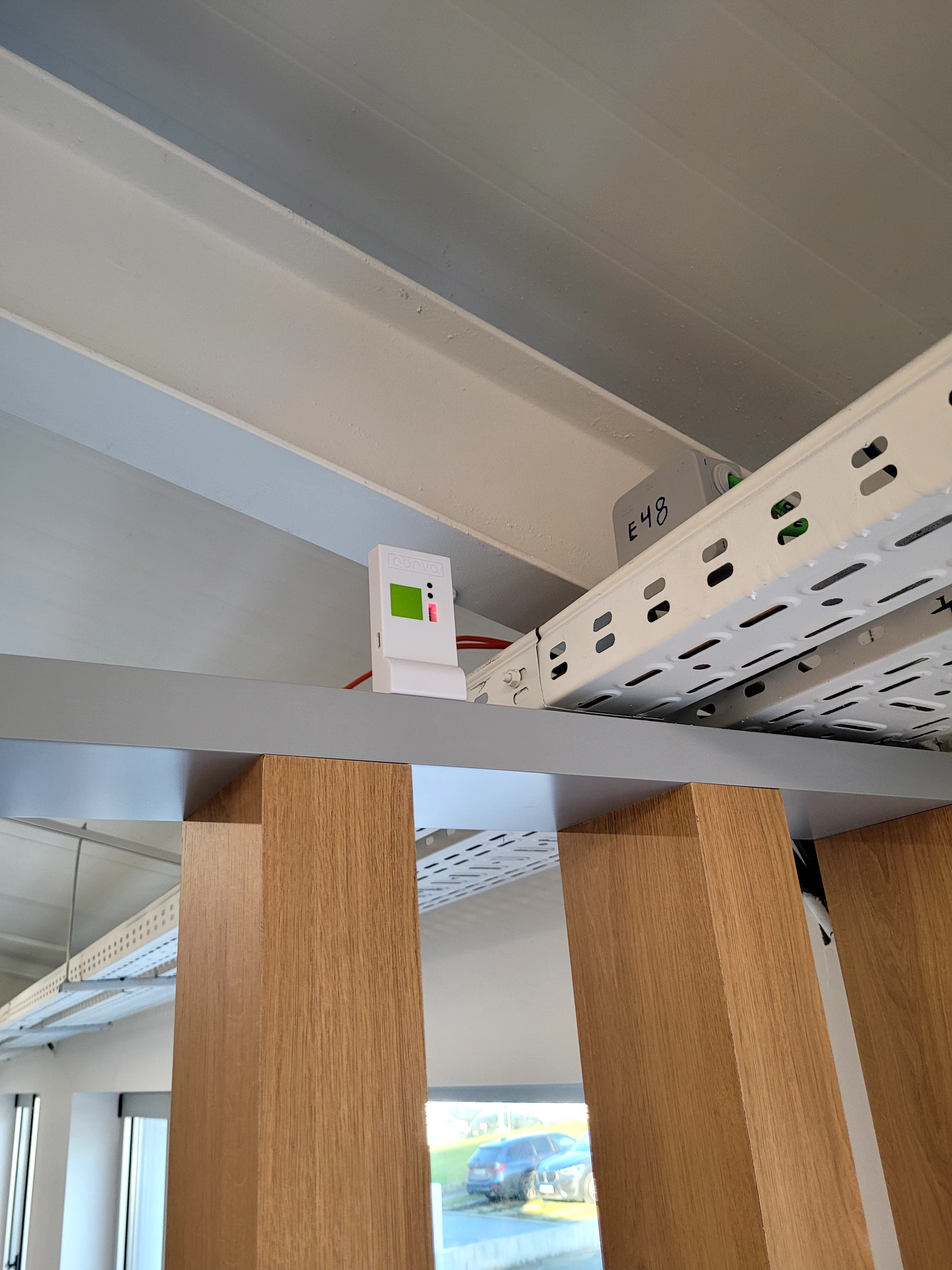
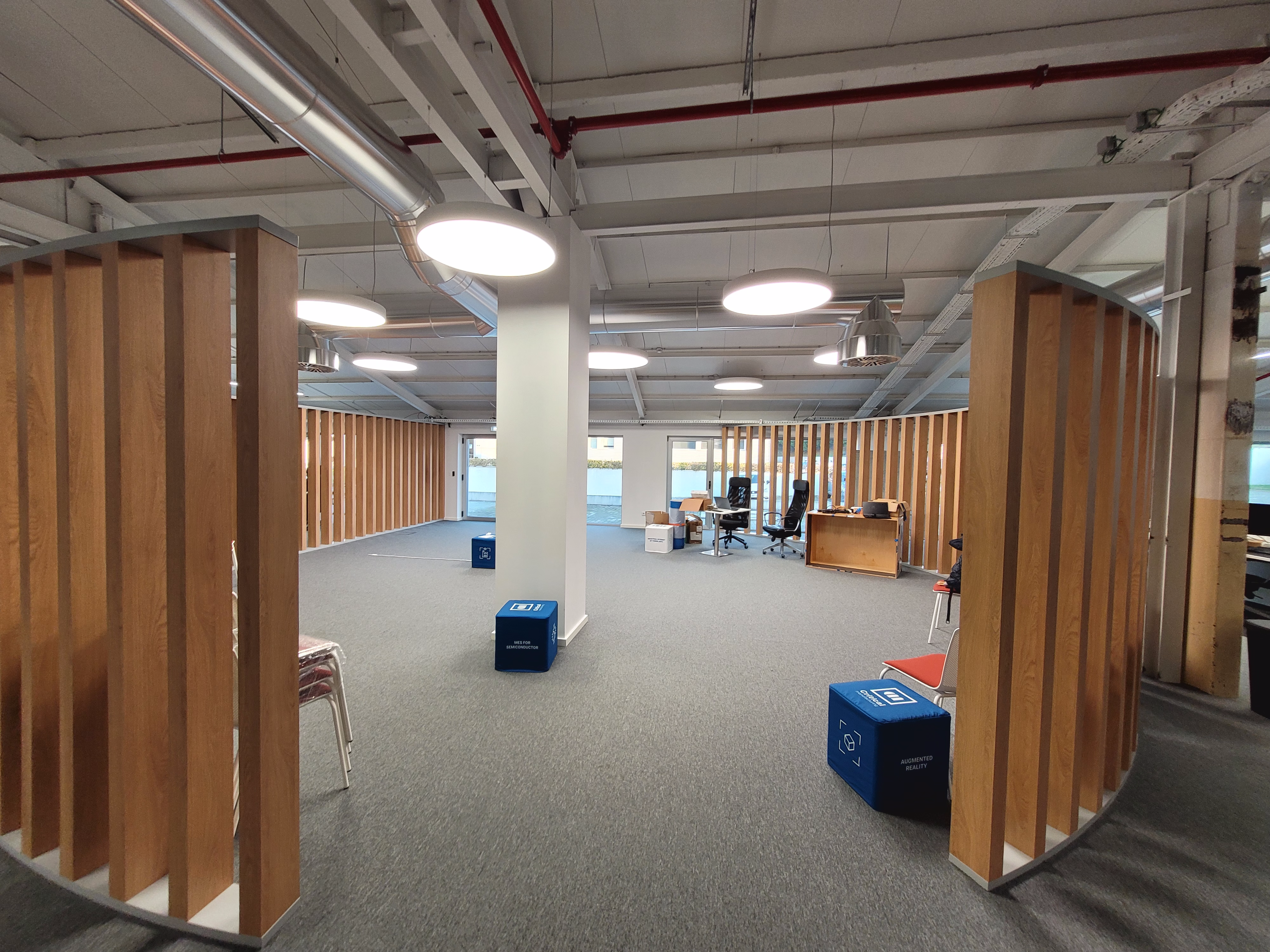
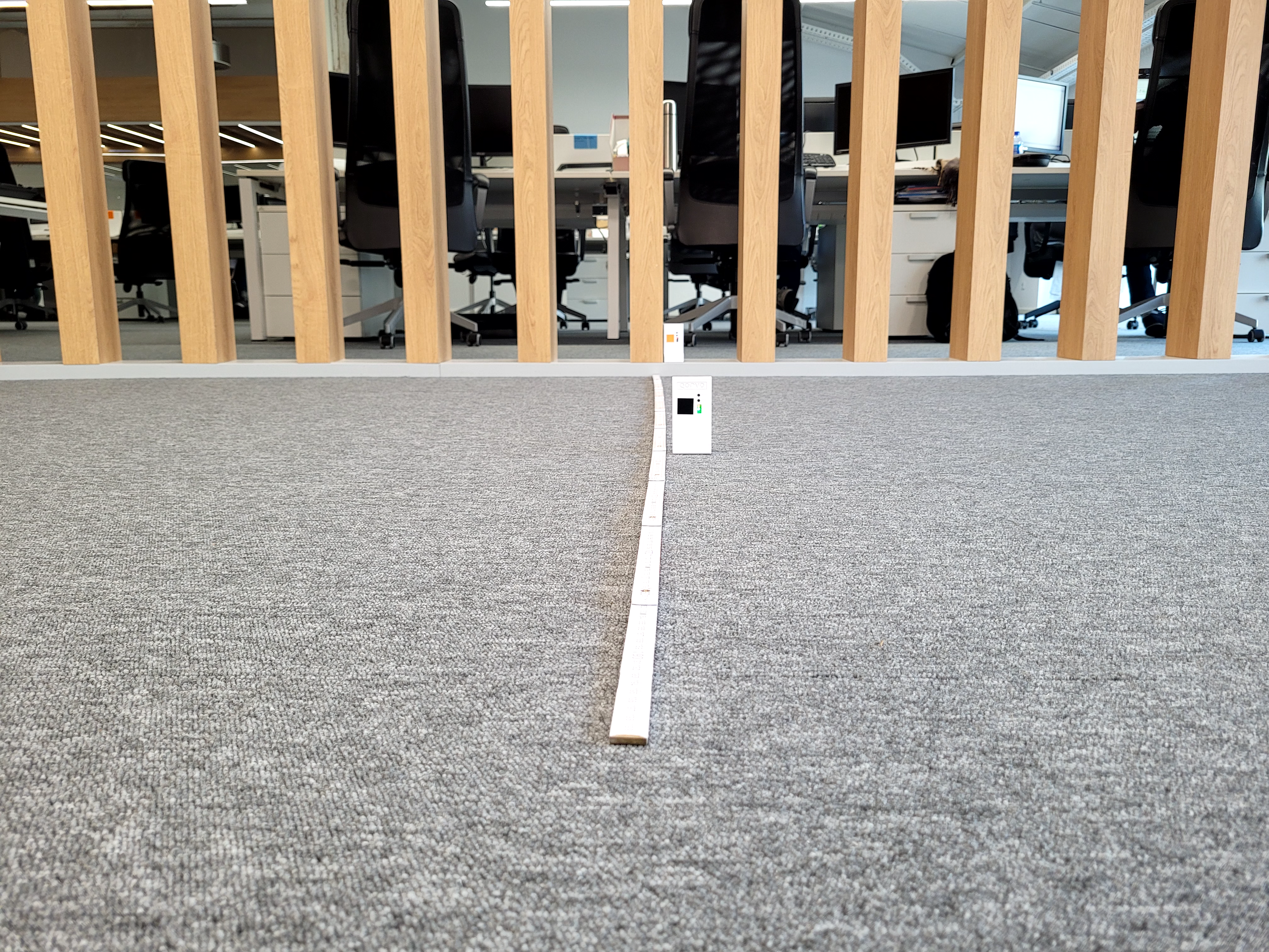
During this test, we set up our system within the company’s environment, broadcasting MQTT messages that were interpreted by the company’s systems. We successfully configured the gateway, the anchors and the tag, and the messages were correctly read.
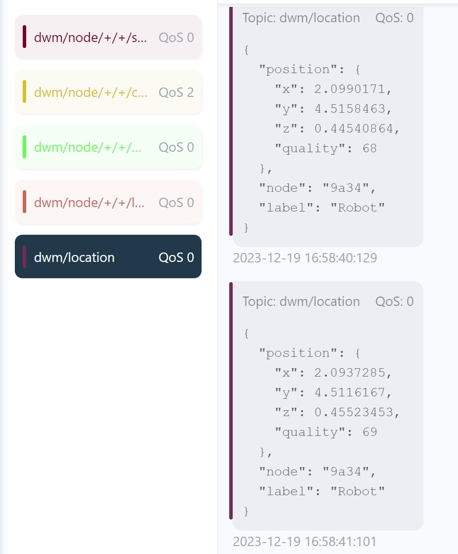
MQTT Location
We have also delivered when it comes to MQTT, with the possibility of collecting the location information via MQTT:
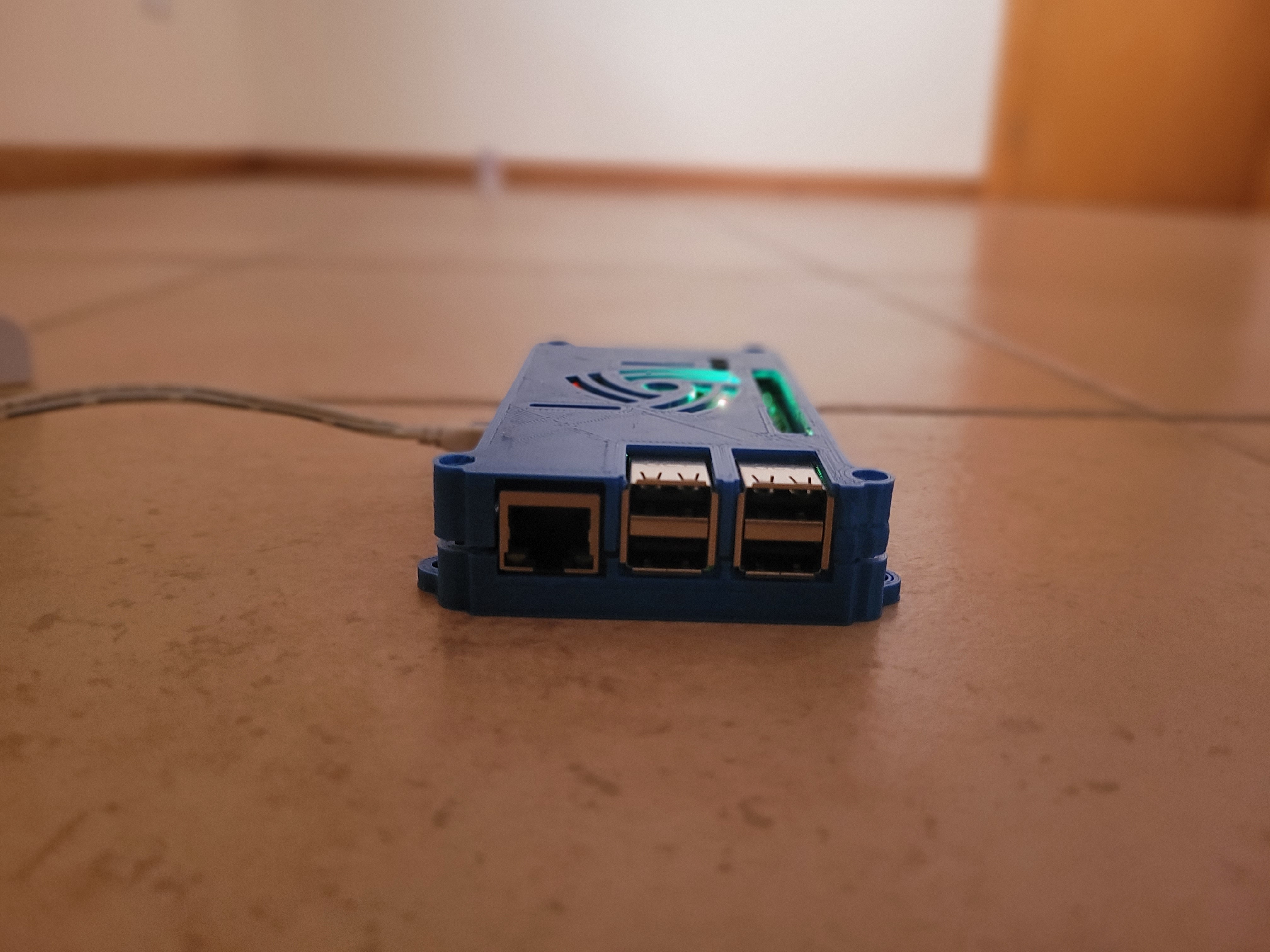
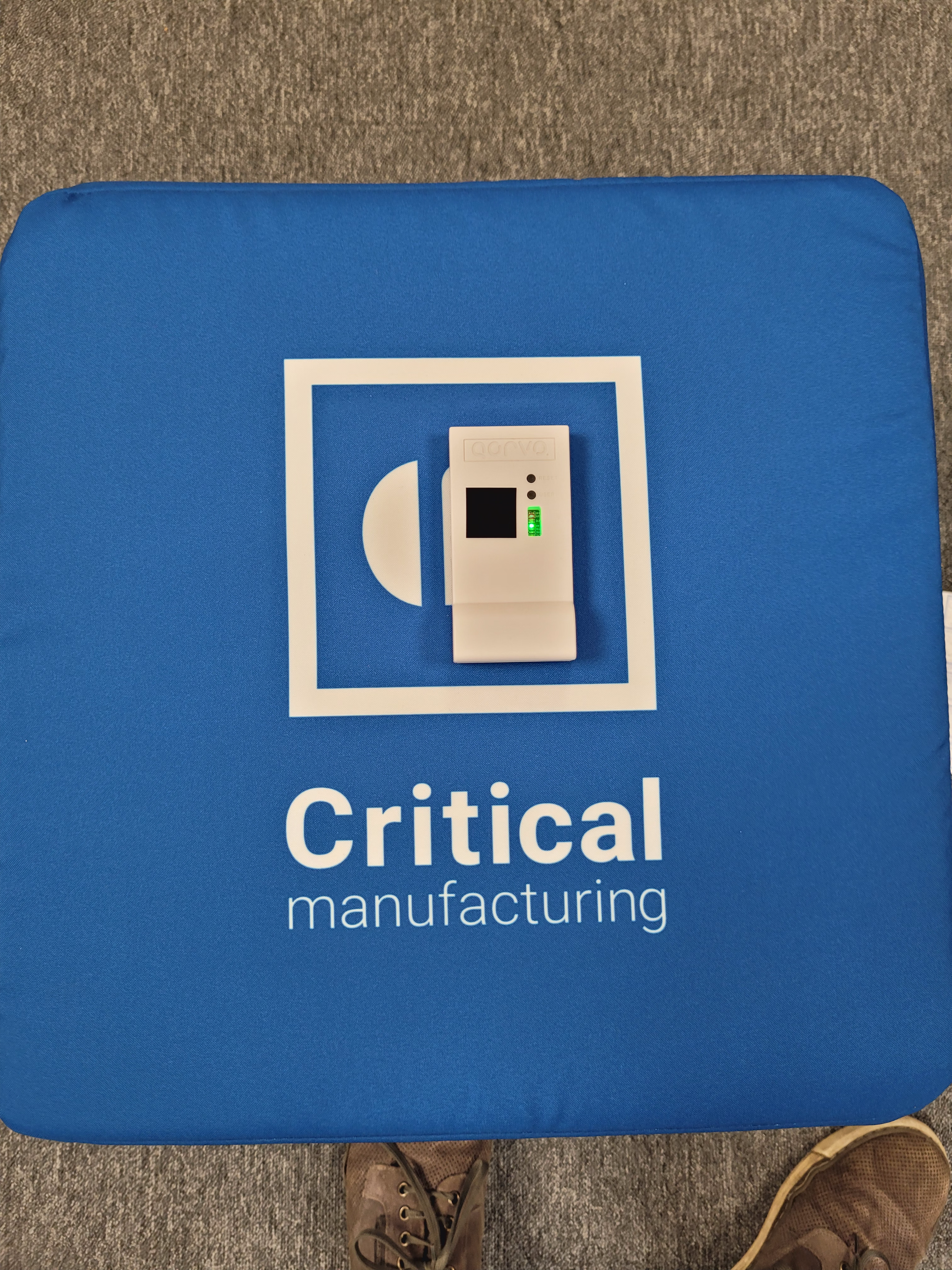
3D Case
But that does not mean our work was done… We printed a 3D case to encapsulate the Raspberry Pi 3 and the UWB module bride node.